")

Computed tomography
The two major application areas of 3D X-ray computed tomography (XCT) in science and industry are material characterization and dimensional measurements (metrology).
The principle of 3D computed tomographyIn principle, a 3D-Computertomograph consists of 3 components, the x-ray source, a rotary table on which the sample is mounted and a digital detector, as shown in Figure 1. The x-ray source emits an x-ray beam witch spreads cone-shaped. When the x-ray beam penetrates the sample the intensity is attenuated depending on the sample thickness, the density and atomic number of the material. The digital detector converts the x-ray intensity into a digital projection image.
To get a 3D-Image of a sample, a full rotation of the sample within the x-ray beam is essential, so the rotary table stops every angle Depending on the quality of the 3D-Dataset and the sample, 1000-2000 projections are needed to create a 3D-Dataset. |
||
|
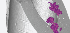
To analyse a 3D-Dataset (also called Voxel-dataset), special software is needed. This Software splits the Volume-data into Axial, Frontal and Sagittal slices to display the results on screen, similar to a metallographic preparation. These three slices are orientated to the global coordinate system of the 3D-Dataset. Axial means a slice in X-Y, Frontal in X-Z and Sagittal in Z-Y direction. By different rendering-algorithms, the software can also display a 3D-Image of the measured sample. The different grey values correspond to the material density whereas high density leads to a bright representation and low density to a dark one.
To archive a height resolution, the sample has to be as close to the tube as possible. Further, that means that the diameter of the sample (max. penetration length) determines the maximum Voxelsize of the CT-Measurement (Resolution = Diameter / 2300 on CT GE phoenix|x-ray nanotom and max. Diameter / 1000 on RayScan 250E). In Figure 2 the dependence of the resolution do to the sample diameter is shown.
|
Hauptvorteile
- Werkstücke und Bauteile können mit einer Genauigkeit bis zu 500 Nanometer auf eventuelle Fehler untersucht werden.
- Bauteile können auch im Inneren exakt untersucht und vermessen werden, ohne sie dafür zu zerschneiden oder zu beschädigen.
- Es können Bauteile aus den unterschiedlichsten Materialien und Materialkombinationen wie Stahl, Aluminium, Magnesium und Kunststoffe untersucht werden.
- CT bietet die Möglichkeit, Bauteile vergleichsweise rasch zu digitalisieren und einen Soll-/Ist-Vergleich mit CAD-Daten für Reverse Engineering oder Rapid Prototyping durchzuführen.
- Das gesamte Bauteil wird innerhalb relativ kurzer Zeit (ca. 30 Min.) komplett vermessen, unabhängig von seiner Geometrie. Auch die Innengeometrie wird mit CT erfasst, was sonst mit keinem Messverfahren möglich ist.
- Da CT ein berührungsloses Verfahren ist, können auch weiche und verformbare Bauteile tomografiert werden.
Hauptanwendungsfelder
- Zerstörungsfreie Werkstoffprüfung und Gefügeuntersuchungen
- Messung von Porositäten sowie Faserlängen und Faserorientierungsverteilungen
- Zerstörungsfreie 3D-Vermessung, insbesondere von Innenflächen (z. B. Messung von einzelnen Messmerkmalen, Wandstärkenmessung, automatisierte Auswertung von Parametersätzen mit Prüfprotokoll, ...)
- Soll-/Ist-Vergleich von CAD-Daten mit CT Messdaten und Duplizierung von Prüfobjekten mittels Rapid-Prototyping-Verfahren
- Generierung von Messdaten für die Simulation von Bauteilen
- In-situ-Untersuchungen von Prozessen